IPv4 Addressing Scheme Design
Welcome, to IPv4 network design.
We’re all very familiar with IPv4, you’ve probably been working with it for years, and you may even have a pretty solid addressing plan in your network currently. In this video, we’ll first do a brief overview of some more technical aspects of IPv4 addressing and subnetting, and then how to use those to design a repeatable plan that you can use within your network design. This is a plan that should be scalable and relatively easy to identify the purpose of the network in question. So without further ado, let’s jump right in.

IPv4 Address Dotted Binary Format
The IPv4 address contains 32 bits of addressing space. This is broken up into 4 octets of 8 bits each to simplify writing it out in dotted decimal notation. The address itself is comprised of a network identifier and host identifier within that network. So like the network is the street you live on and the host is the house number you live in.

Subnet Mask Dotted Binary Format
The thing that defines which portion of the address is the network identifier and which is for the host is the subnet mask. Moving from left to right, all parts of the mask which are a 1 indicates that respective bit in the address field is a bit which is part of the network identifier. The remaining 0s in the subnet mask indicate that respective bit in the address field is a member of the host identifier. I mean this makes sense once you realize that computers talk in binary and that fundamentally that’s what all the communication is in, right? So it receives this address that’s 32 bits, all being 1s and 0s, and then receives a mask which is a certain number of 1s in a row to indicate what part of that address is the network and what part is the host.

Calculating the network ID for an address
Now I mentioned dotted decimal notation already, but we didn’t talk about CIDR. It’s pronounced "cider", and stands for classless inter-domain routing. This notation expresses the subnet mask with a forward slash and a number which corresponds to the number of 1s in the subnet mask. This is often referred to as the prefix length. A lot of people for simplicity sake go with the /24 network, to go at the bit boundary to allow for nice clean subnetting; but sometimes we forget that it doesn’t have to actually be this way. We can certainly do a /21 network instead, allowing 3 more bits for the host address, meaning we can now have 2046 host addresses; when you consider the first address in the subnet is the network identifier, with all the host bits being 0s, and the last address is the broadcast address for the network, with all the host bits being 1s.
I wanted to take this chance to go over subnetting, and specifically how one determines what the network identifier address is for a subnet. Say you’re given this address, 172.16.10.5/21 and you want to find what the network ID is. Well you can do this 1 of 2 ways really. The easiest is to write it out in binary. On top we have the address, and below it the mask which is 21 1s in a row. Here you do a logical AND operation between them. What that means is if both the subnet bit and the corresponding address bit are a 1, then the resulting bit is a 1, if they differ or are 0s, then they’re 0. We find that what this does it give us the same bits up to where the subnet mask turns to 0s, and the remaining bits are all 0s. If you convert this into decimal, you get 172.16.8.0/21. I find this is really the best way to learn because it lets you visualize what’s really happening with a subnet mask.

21 bit subnet mask
Now the second method is to determine what the stepping interval is of the networks. Here in the 3rd octet we have 3 bits for the host identifier. So we count the value places in binary, 1, 2, 4, 8 up to where we get the first 1 in the mask. So we know since that’s where the first 1 is in the mask, the network IDs will step by 8s. so it’ll be 172.16.0.0/21, then 172.16.8.0/21, then 172.16.16.0/21, etc.

RFC 1918 Private Address Spaces
Hopefully you’re aware of private addressing in IPv4, but I wanted to review what address spaces we have available to us in our designs. Of course the reason private address spaces are called private and are reserved is because these address spaces do not uniquely identify a device on the internet and therefore is not routable on the internet.
We have 3 classes of networks in the private addressing space. Class A is one large /8 network using the 10.0.0.0/8 space. Class B private networks are /12 networks; and the space which is used for class B networks is 172.16.0.0 to 172.31.255.255 which contains 16 class B networks. And finally class C networks are /24 networks and the space available is 192.168.0.0 to 192.168.255.255 which provides for 256 class C networks.
Now, this might feel a bit strange to you because we don’t often deal with classful routing anymore; you can certainly subnet a class B address space into a /24, using 172.16.0.0/24 for example; or make a smaller network if you don’t need 254 host addresses available, we just want to be aware of the address space available for us to use in private addressing.
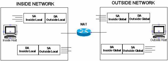
Cisco NAT Terminology
Now network address translation is the saving grave of IPv4 and is the only reason that IPv4 is still around and more people haven’t migrated to IPv6 yet. With network address translation there’s 3 main flavors, static NAT, dynamic NAT, and port address translation which is also called NAT overload. With static NAT you’re creating a static entry in the router or firewall and the traffic is always translated the same way, the router does not keep track of the translated packet at all after it passes through, this is called stateless NAT. With dynamic NAT and PAT, the router keeps a table of what translations have occurred so it can continue to provide consistent translation for the return traffic. Dynamic NAT is a 1-to-1 translation where a single inside host computer is assigned a single outside IP address and all traffic to/from that IP is translated to that host for the life of the table entry, which usually has an inactivity timeout to free up the IP. PAT is what we commonly use to provide internet access which maps many inside source IP and port combinations, to a single outside IP, but adjusting the source port on the translated source to keep track of what return traffic goes to which inside host. It’s pretty ingenious and allows for tens of thousands of concurrent active connections assuming your router can handle the traffic. In the upper-right here I’ve put the NAT terminology Cisco uses, I haven’t seen this on a CCDA exam, but it wouldn’t hurt to review briefly to stay aware of what these terms means.
Great, so now that we’ve done an overview of some of IPv4’s characteristics we can get into the design recommendations. A first best practice to know and be aware of is that you should always separate your voice and data traffic into 2 separate VLANs. Nearly all businesses now are using VOIP and to allow for easier QoS configuration and congestion monitoring, you should use a separate network for your voice traffic. Now, at some point, your addressing plan will blow up; if you keep growing that is. There’s only so much addressing space and you can only conserve addresses so much without causing yourself all kinds of headache. I mean just looking at the example addressing scheme here, you can see, what happens if you go above 256 sites? Or above 254 devices in one of the sites? Then your continuous addressing plan blows up and you start having to re-address or through in a non-continuous subnet or something like that. So that’s why we want to generally split up our functions into different subnets as well, to reduce the likelihood that you’ll be exceeding whatever your device limit is with that particular function.
Now, one of the golden rules of address planning is to design with summarization in mind. As our business grows and you have your dynamic routing protocols distributing your routes, you don’t want a wiring closet change to end up propagating through your entire enterprise. We summarize because that essentially sets the boundary for where routing updates stop for OSPF, and where query messages stop for EIGRP.

poor addressing plan for a global organization
If you didn’t end up planning your addressing scheme with summarization in mind, you might end up with a network that looks something like this. Now of course your enterprise doesn’t need to be worldwide to end up with a large network, but you see how we have noncontiguous networks coming out of the various countries here. No of course, this happens, right, where first you have a few offices in Asia, then you branch out to Europe, and those offices get really big so you make it a /21. But then Asia gets bigger and you add a /22 there, and then you branch out into the Americas, so on and so forth. You’ll almost never come into a blank slate or greenfield environment and design a new addressing scheme, you’ll have to do the best you can to plan for growth while designing with summarization in mind.

much better addressing plan for the same organization
In this same example if we had used contiguous networks throughout, we could make our routing nice and clean, just having these /18 networks advertised out from each area here into the core. It’ll look nice, your core routing table will be clean and concise and small, and it’ll just feel good. Here, we even still have a lot of room for growth in each area, we haven’t come close to using all of the addresses available in each /18, so you know you won’t run into problems, at least not anytime soon.

role-based vs. bit splitting addressing
So, Cisco recommends for address planning to use role-based addressing. Where you have 10.x.y, where x is the wiring closet number, building number, floor number, etc, just x is the location identifier here, and y is the function of the vlan at that location. This allows for not only summarization of each location into the distribution and core, but also easy identification of what an address is used for. You can use VLAN 10 for data, VLAN 11 for voice, 12 for printers, 13 for wifi, etc. Your excel sheet you made of your address plan will be clean and tidy and very readable and easier to understand. This feels simple, but also as you can see, it’s also likely this will end up with some address wastage. The way to minimize that is to go about the more difficult method of addressing called bit-splitting. This really comes into place when you’re using subnets that don’t end at the bit boundary, so using something smaller than a /24 regularly. The best way to organize this in your spreadsheet is really by binary. You can have the dotted decimal equivalent on a column, but in another column to have the network line up well and understand which network corresponds to what function easily you can list the binary equivalent of the network portion. It might be more tedious, but you’ll end up with much tighter subnets and less address wastage. Just make sure you plan appropriately to ensure your plan won’t blow up when you start needing more devices on the network than you have addresses available.

In the last slide here I wanted to do a brief case study to bring this together in a more real-world example. Let’s consider the apple store, right. Here’s how I would design their network. So I did reverse Cisco’s simple addressing plan a bit but I’ll show you why. First, the data vlan is for their internal devices, like the genius bar computers and POS systems, the automatic screen repair machines and perhaps the security devices and cameras as well. Of course they use VOIP so we’ll want a separate subnet for that. Then the internal wifi for the handheld iphones and all that they use to checkout and for the staff’s devices to connect to. I like to create a separate vlan for servers and printers, the POC servers, security system, printers for the repair shop in the backoffice. The exit VLAN, this is a little point to point network that all is does is connect the layer 3 switch to the firewall or router, this is a vlan that will never see the light of day and never needs to be able to be addressed from anywhere else in the enterprise. The same goes for the public wifi. Now this subnet is so huge because, 1 we can do it, and 2 because Apple has these huge product launches, right? Where hundreds or thousands of people are waiting outside to get he new iPhone and they all have their existing phones and want to connect to the Wifi. Then finally of course we have the management VLAN.
Now the reason why I started at 0 up here is because these 4 VLANs here are ones that need to be routable across the enterprise. So we can take these 4 and summarize them into 10.0.0.0/14 and say that’s the Eastern united states, right? Then we can use 10.4.0.0/14 and have that be the Midwest, the 10.8.0.0/14 be the west, so on so forth, and allow for less address wastage and more growth along with summarization.
I thought this might be fun, that’s for sticking with me!
© Ben Jacobson.RSS